- 您现在的位置:买卖IC网 > Sheet目录2000 > ISD5008EYI (Nuvoton Technology Corporation of America)IC VOICE REC/PLAY 4-8MIN 28-TSOP
ISD5008
Publication Release Date: Oct 31 2008
- 14 -
Revision 1.2
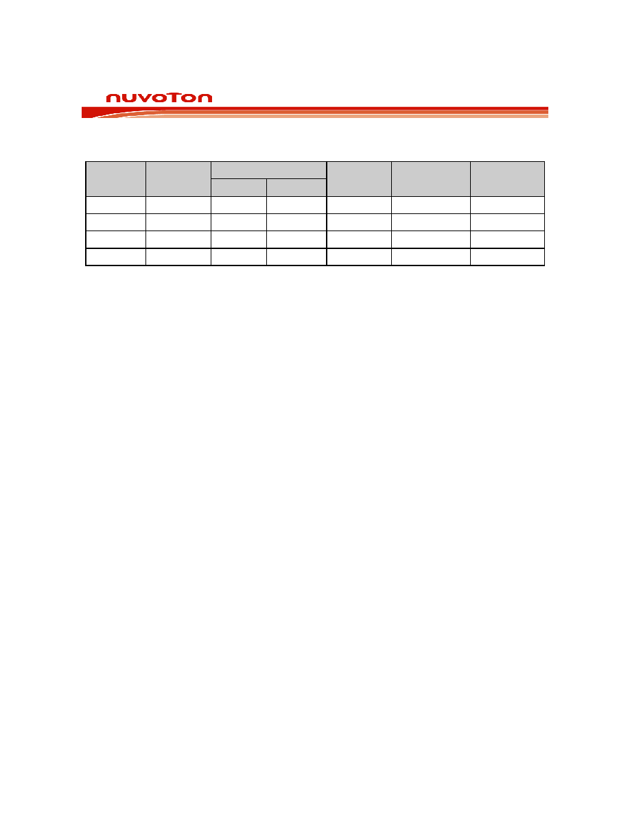
TABLE 5: AUXIN AMPLIFIER GAIN SETTINGS
Setting
(1)
0TLP Input
VPP
(3)
CFG0
Gain
(2)
Array In/Out
VPP
ANA OUT
VPP
(4)
AXG1
AXG0
0 dB
.694
0
1.00
.694
3 dB
.491
0
1
1.41
.694
6 dB
.347
1
0
2.00
.694
9 dB
.245
1
2.82
.694
NOTES:
1.
Gain from AUX IN to ANA OUT
2.
Gain from AUX IN to ARRAY IN
3.
0TLP Input is the reference Transmission Level Point that is used for testing. This level is typically 3 dB
below clipping.
4.
Differential
6.2.4
ACAP (AGC Capacitor)
This pin provides the capacitor connection for setting the parameters of the microphone AGC circuit. It
should have a 4.7
μF capacitor connected to ground. It cannot be left floating. This is because the
capacitor is also used for the AutoMute circuit. This circuit reduces the amount of noises present in the
output during quiet pauses. Tying this pin to ground gives maximum gain; to VCCA gives minimum gain
for the AGC amplifier but will cancel the AutoMute function.
发布紧急采购,3分钟左右您将得到回复。
相关PDF资料
ISL12008IB8Z
IC RTC I2C LO-POWER 8-SOIC
ISL12020MIRZ-T7A
IC RTC/CALENDAR TEMP SNSR 20DFN
ISL12022IBZ-T7A
IC RTC/CALENDAR TEMP SNSR 8SOIC
ISL12022MAIBZ
IC RTC/CALENDAR TEMP SNSR 20SOIC
ISL12022MIBZ-T7A
IC RTC/CALENDAR TEMP SNSR 20SOIC
ISL12022MIBZR5421
IC RTC/CALENDAR TEMP SNSR 20SOIC
ISL12023IVZ
IC RTC/CLDR TEMP SNSR 14-TSSOP
ISL12024IRTCZ
IC RTC/CALENDER 64BIT 8-TDFN
相关代理商/技术参数
ISD5008P
功能描述:IC VOICE REC/PLAY 4-8MIN 28-DIP RoHS:否 类别:集成电路 (IC) >> 接口 - 语音录制和重放 系列:ISD5008 标准包装:14 系列:- 接口:串行 滤波器通频带:1.7kHz 持续时间:8 ~ 32 秒 安装类型:通孔 封装/外壳:28-DIP(0.300",7.62mm) 供应商设备封装:28-PDIP 其它名称:90-21300+000
ISD5008PY
功能描述:IC VOICE REC/PLAY 4-8MIN 28-DIP RoHS:是 类别:集成电路 (IC) >> 接口 - 语音录制和重放 系列:ISD5008 标准包装:14 系列:- 接口:串行 滤波器通频带:1.7kHz 持续时间:8 ~ 32 秒 安装类型:通孔 封装/外壳:28-DIP(0.300",7.62mm) 供应商设备封装:28-PDIP 其它名称:90-21300+000
ISD5008S
功能描述:IC VOICE REC/PLAY 4-8MIN 28-SOIC RoHS:否 类别:集成电路 (IC) >> 接口 - 语音录制和重放 系列:ISD5008 标准包装:14 系列:- 接口:串行 滤波器通频带:1.7kHz 持续时间:8 ~ 32 秒 安装类型:通孔 封装/外壳:28-DIP(0.300",7.62mm) 供应商设备封装:28-PDIP 其它名称:90-21300+000
ISD5008SD
制造商:未知厂家 制造商全称:未知厂家 功能描述:SINGLE CHIP VOICE RECORD PLAYBACK DEVICE 4-, 5-, 6-, AND 8- MINUTE DURATIONS
ISD5008SERIES
制造商:未知厂家 制造商全称:未知厂家 功能描述:Single-Chip Voice Record/Playback Device
ISD5008SI
功能描述:IC VOICE REC/PL 4-8MIN IN 28SOIC RoHS:否 类别:集成电路 (IC) >> 接口 - 语音录制和重放 系列:ISD5008 标准包装:14 系列:- 接口:串行 滤波器通频带:1.7kHz 持续时间:8 ~ 32 秒 安装类型:通孔 封装/外壳:28-DIP(0.300",7.62mm) 供应商设备封装:28-PDIP 其它名称:90-21300+000
ISD5008SIR
功能描述:IC VOICE REC/PL 4-8MIN IN 28SOIC RoHS:否 类别:集成电路 (IC) >> 接口 - 语音录制和重放 系列:ISD5008 标准包装:14 系列:- 接口:串行 滤波器通频带:1.7kHz 持续时间:8 ~ 32 秒 安装类型:通孔 封装/外壳:28-DIP(0.300",7.62mm) 供应商设备封装:28-PDIP 其它名称:90-21300+000
ISD5008SY
功能描述:IC VOICE REC/PLAY 4-8MIN 28-SOIC RoHS:是 类别:集成电路 (IC) >> 接口 - 语音录制和重放 系列:ISD5008 标准包装:14 系列:- 接口:串行 滤波器通频带:1.7kHz 持续时间:8 ~ 32 秒 安装类型:通孔 封装/外壳:28-DIP(0.300",7.62mm) 供应商设备封装:28-PDIP 其它名称:90-21300+000